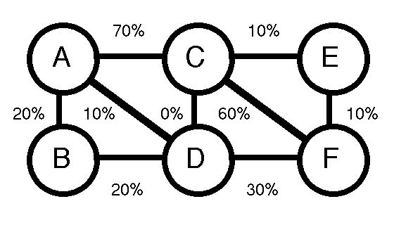
The following 6 area system will be used to evaluate a MW transfer from Area A to Area F.

The following table describes the PTDF's, the ALC's and the inter/intra-area ATC's required to evaluate a MW transfer from Area A to Area F.
| Inter/Intra-Area Interface | Network Response PTDF (%) | Available Loading Capacity (ALC) on Limiting Facility (MW) | Inter/Intra-Area ATC (MW) | Area A to Area F System ATC (MW) |
|---|---|---|---|---|
| Area A | 10 | 100 | 1000 | |
| Area B | 10 | 200 | 2000 | |
| Area C | 20 | 300 | 1500 | |
| Area D | 20 | 100 | 500 | 500 |
| Area E | 10 | 200 | 2000 | |
| Area F | 10 | 100 | 1000 | |
| A - C | 70 | 490 | 700 | |
| A - D | 10 | 120 | 1200 | |
| B - A | -20 | -360 | 1800 | |
| B - D | 20 | 140 | 700 | |
| C - E | 10 | 210 | 2100 | |
| C - F | 60 | 660 | 1100 | |
| D - C | 0 | 50 | inf | |
| D - F | 30 | 270 | 900 | |
| F - E | -10 | -130 | 1300 |